ATEX marking:
how to select Ex equipment
[GUIDE + WORKBOOK]


The problem of understanding Ex markings on explosion-proof equipment is huge. This is evidenced not only by daily interactions with customers, but also by the fact that our guide that explains this issue has already been downloaded 10,000 times. Today we have prepared a guide to this issue with tasks that will give you the necessary foundation for the correct selection and operation of Ex equipment. This will protect you from costly and, above all, dangerous mistakes.
NOTE: before we move on to the main part of the article, let us clarify a few terms:
| Concept | Meaning |
|---|---|
| Ex / explosion-proof equipment | Any equipment or component designed for operation in an explosion hazardous area. |
| Ex marking | A string of symbols placed on the nameplate, in the declaration of conformity and in the type-examination certificate (if required has been issued), which informs about the place of possible installation of the equipment, the safety features used in it to reduce the risk of ignition of an explosive atmosphere and the conditions of its use. |
| ATEX certificate | The colloquial term for a type-examination certificate, that is, a document confirming a positive result of a conformity assessment of equipment performed by a notified body with the participation of a notified body. |
NOTE: not every piece of equipment intended for explosive atmospheres must be ATEX certified (formally known as a type-examination certificate). For an explanation in this regard, see the article titled: Must all Ex equipment be ATEX certified?
Special marking of Ex equipment: what is the legal basis?
Manufacturers of equipment for explosive atmospheres must comply with the requirements of the ATEX Directive (2014/34/EU), the provisions of which were introduced into our legislation by the Ordinance of the Minister of Development of June 6, 2016 on requirements for equipment and protective systems intended for use in potentially explosive atmospheres (Journal of Laws 2016 item 817). This regulation implies, among other things, the obligation to include special markings on nameplates, in the declaration of conformity and in the type test certificate (if issued), which are referred to as the Ex marking.
An example of an Ex marking with an explanation of the various designations:
- equipment group
- category of equipment
- confirmation that the equipment is designed as explosion-proof
- type of explosion protection
- explosion subgroup of dust/gas/vapors for which the equipment is intended
- temperature class (gases and vapors) and/or maximum surface temperature (dust)
- equipment protection level (EPL)
Ex marking: the meaning behind the symbols
The individual elements that make up the explosion-proof marking of equipment can be divided into two groups:
- symbols necessary for the correct selection of equipment for operation in a hazardous area; they specify in which conditions the equipment can be used
- symbol informing what safeguards have been used in the equipment to eliminate sources of ignition; often have impact on the cost of purchase, installation and operation of the equipment
The purpose of this article is to help you select equipment for operation in a given hazardous area (point 1) in a safe manner, and thus in compliance with applicable regulations. Since the explanation of the dependencies and consequences of the second point is an extensive topic we will describe it in a separate article.
Examples of Ex marking
Below is an example of the explosion-proof marking of the HARDO OptiLine luminaire. This luminaire can operate in explosive atmospheres generated both by flammable gases and vapors of flammable liquids and by flammable dusts. For this reason, we have presented the designations in two lines – separately for gases and vapors and separately for dusts.
| [DUSTS] | II 2D Ex tb IIIC T70°C Db |
| [GASES/VAPORS] | II 3G Ex ec IIC T4 Gc |
What to focus on when selecting equipment for a hazardous area
Below you will find tables with explanations of each element of the explosion-proof marking. The green color indicates that a given value is derived from the above designation, which you will find on the nameplate, declaration of conformity and in the type test certificate (commonly referred to as ATEX certificate). These markings, as we mentioned earlier, tell us about the conditions under which a given device can be used safely. They are therefore crucial to the correct selection of an Ex device in terms of safety and regulatory compliance. They are what we will focus on in the following section.
Equipment group
| I | Equipment designed for use in underground mines |
| II | Equipment intended for use in non-mining plants |
Equipment category
Depending on whether we are dealing with a piece of equipment operating in a mining plant or in a non-mining plant (see equipment groups above), equipment is assigned different categories. These indicate under which conditions (Group I) or in which explosion hazard zone (Group II) the equipment can be used.
Categories for equipment group I
| M1 | Mining facilities: devices that can operate even in the event of rare faults. The required level of protection will be provided in case of two independent failures | |
| M2 | Mining facilities: ignition sources associated with this device must not become active even under the most severe operating conditions, especially those resulting from careless handling and changing environmental conditions. The device will shutdown in the event of an explosive atmosphere |
Categories for equipment Group II
Which category a manufacturer can qualify a device for depends on the level of safety guaranteed by the device.
Devices can be designed for operation in gas and/or dust zones. Therefore, in the designation on the nameplate next to the category of the device, the letters D and/or G are added, where:
- D – dust atmosphere
- G – gas (or flammable vapor)
| 1G | Equipment designed for zones 0, 1 and 2 generated by gases or vapors. | level of safety. The device does not cause any effective sources of ignition even during occasional malfunctions. | |
| 1D | Equipment designed for zones 20, 21 and 22 generated by dust. | ||
| 2G | Equipment designed for zones 1 and 2 generated by gases or vapors | High level of safety. The device does not cause any effective sources of ignition even during an expected malfunction. | |
| 2D | Equipment designed for zones 21 and 22 generated by dusts; | ||
| 3G | Equipment designed for zone 2 generated by gases or vapors | Normal poziom bezpieczeństwa. Equipment does not cause any effective ignition sources during normal operation. | |
| 3D | Equipment designed for zone 22 generated by pyły dusts; |
NOTE 1: In some cases, equipment may have different categories in different places, such as another in its interior and another outside. An example would be a fan that has a 2D category inside (this means that there may be a zone 22 or 21 in the duct), while outside it has a 3D category (it may be installed in zone 22). As a result, the designation of such a fan will look like this: 2/3D.
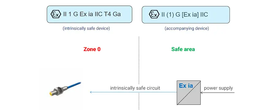
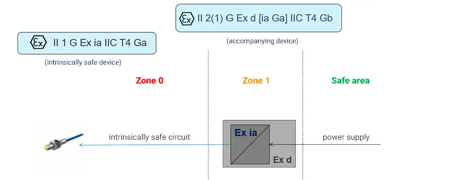
NOTE 2: in intrinsically safe circuits, we may have to deal with a so-called associated device (intrinsically safe barrier or separator). This means that this device is designed to work with an intrinsically safe device installed in a hazardous area, and itself, depending on the design, may be located in another zone or in a safe space.
The marking of the companion device will include the category and type of protection of the device with which it can cooperate. Whereby the said category will be in round brackets, while the type of protection will be in square brackets (see table below). If the associated device is intended for:
- installation outside the hazardous area, only the category and type of protection of the device with which it can operate (in parentheses) will be in the marking
- installation in a hazardous area – then in the marking, in addition to the category and type of protection of the device with which it can cooperate (point 1 above) will be its own category and type of protection placed outside the parentheses
Example of Ex marking for a connection of an associated Ex device for intrinsically safe circuits
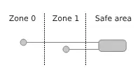
| Zone 0 | Zone 1 | Safe zone |
| II 1G Ex ia IIC T4 Ga Marking of an intrinsically safe equipment | II (1)G [Ex ia Ga] IIC Marking of an associated equipment | |
| II 1G Ex ia IIC T4 Ga Marking of an intrinsically safe equipment | II 2(1)G Ex d [ia Ga] IIC T4 Gb Marking of an associated equipment |
Visual example 1
Visual example 2
Examples of equipment categories:
| Designation | Explanation | Where to use | |
| Ex II 1 D | Group II equipment for use outside mines, category 1 dust | Installation in zone 20 |

|
| Ex II (1) G D | Group II equipment, associated equipment, for use with category 1 dust and gas equipment | Mounting outside Ex zones, works with device mounted in zone 0 or 20 |
|
| Ex II 2 (1) G | Group II appliance, associated appliance category 2, for use with category 1 gas appliance | Mounted in zone 1, cooperates with device mounted in zone 0 (e.g. cooperating device mounted in zone 1) |
|
| Ex II (2) G (1) G | Group II appliance, associated equipment, for use with category 1 gas and category 2 gas appliance | Mounting outside the Ex-zone, works with device mounted in zone 1 and device mounted in zone 0 |
|
| II 1/2 G | Group II equipment, part of equipment category 1, part of category 2 gas | Mounting at zone boundaries, part of the unit operates in zone 0, part in zone 1 (e.g. sensor mounted in tank wall between zones 0 and 1) |
|
| II 3/3 D | Group II, category 3 device inside and outside the device | Mounting at zone boundaries, inside the unit zone 22, outside zone 22 (e.g. fan with zone 22 inside, mounted in zone 22) |
|
| II 2/- G | Group II, category 2 device inside | Mounting at zone boundaries, inside the unit zone 1, outside no Ex-zone (e.g. fan with zone 1 inside mounted outside Ex-zone) |
|
| II -/3 D | Group II, category 3 device outdoors | Non-explosive atmosphere equipment, Zone 22 installation (e.g. fan, non-explosive atmosphere switch mounted in Zone 22) |
|
| II 3 G II 2 D |
Group II, Category 3 gas and Category 2 dust equipment | Installation in zone 2 or zone 21 |

|
| GD | Protective system for use in gas/vapour/dust atmospheres | Installation in zone 0, 1, 2 or in zones 20, 21, 22 |
|
How to determine the required category of the equipment?
To know what category the equipment should be in, you need to check in which explosion hazard zone it will operate.
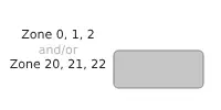
According to the ATEX USER Directive (1999/92/EC), electrical and non-electrical equipment with an appropriate category should be used in explosive atmospheres, selected according to the type of hazard zone:
– in Zone 0, only equipment category 1G
– in Zone 0, only equipment category 1G lub 2G
– in Zone 2, equipment category 1G, 2G or 3G
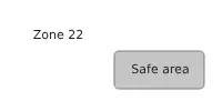
– in Zone 20, only equipment category 1D
– w strefie 21, equipment category 1D or 2D
– w strefie 22, equipment category 1D, 2D or 3D
Zones are determined on the basis of applicable national standards taking into account the following aspects:
- For gas zones
- substance properties
- possible sources of emissions that can cause an explosive atmosphere
- degree of emission (continuous, first or second)
- velocity of air flow over the emission source
- degree of dilution
- dostępność/niezawodność wentylacji
- przeszkody fizyczne
- For dust zones
- substance properties
- possible sources of emissions that can cause an explosive atmosphere
- size of dust particles (granularity)
- specific density of the dust
- humidity of the dust
- pressure in the equipment containing the dust
- location and size of the opening through which emission occurs
- emission efficiency
- presence of exhaust ventilation
- any mechanical obstructions
- cleaning operations applied (effectiveness of cleaning)
The classification is to indicate the areas within the installation where an explosive atmosphere may occur. Depending on the time or frequency of its occurrence, we can designate the following zones:
| ZONE 0 | Explosive atmosphere is present constantly, frequently or for long periods of time |
| ZONE 20 | |
| ZONE 1 | Explosive atmosphere can sometimes occur during normal operations |
| ZONE 21 | |
| ZONE 2 | Explosive atmosphere does not occur during normal operation, and persists for a short period during an occurrence |
| ZONE 22 |
The classification of explosion hazard zones can be found in the explosion risk assessment or explosion hazard assessment documents. According to the ATEX USER Directive (1999/92/EC), the employer is required to draft an explosion risk assessment along with the designation of explosion hazard zones. In practice, this task is often outsourced to external expert companies. As the WOLFF GROUP, over 30 years in the market we have performed several hundred explosion risk assessments for industrial plants from all major industries.
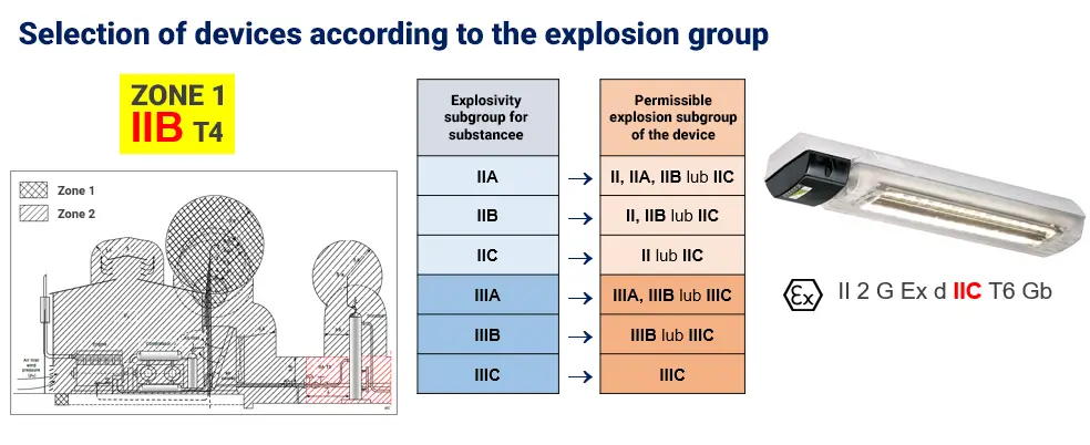
Explosivity subgroup for gases and vapors of flammable liquids
Flammable gases and vapors of flammable liquids are assigned explosion subgroups IIA, IIB lub IIC. They are determined, among other things, by testing the Maximum Experimental Safe Gap (MESG) or Minimum Ignition Current (MIC).
| MESG limit values | Explosion subgroup |
| ≥ 0.9 mm | IIA |
| 0.5 mm < MESG < 0.9 mm | IIB |
| ≤ 0.5 mm | IIC |
| MESG limit values | Explosion subgroup |
| > 0.8 | IIA |
| 0.45 ≤ MIC ≤ 0.8 | IIB |
| < 0.45 | IIC |
How to determine the explosivity subgroup for gases and liquid vapors?
For gases and vapors of flammable liquids, the explosivity subgroup can be found in EN ISO/IEC 80079-20-1 Explosive atmospheres. Part 20-1: material properties for the classification of gases and vapors. Test methods and tabular data. It contains a table with results for more than two hundred substances. If necessary, you can also contact us to refer to our databases.
If the above fails, then to determine the explosivity subgroup according to standard, you need to:
- Perform a laboratory test of the Minimum Incendiary Current (MIC).
- Perform a laboratory test of the Maximum Experimental Safety Gap (MESG), aka the minimum extinguishing gap.
- Determine the subgroup based on the similarity of chemical structure (so-called provisional classification).
As a rule, is sufficient to determine only one of the parameters (most often it is the MIC) to determine the explosivity subgroup. Only if the result is borderline should it be confirmed by determining the second parameter.
How to select equipment for a hazardous area created by gases and vapors of a given explosive subgroup ?
| IIA | Equipment with the IIA designation may be used in explosion hazard zones generated by gases and vapors of subgroup IIA only. | |
| IIB | Equipment with the IIB designation can be used in explosion hazard zones generated by gases and vapors of subgroups IIA and IIB. | |
| IIC | Equipment with the IIC designation can be used in hazardous areas generated by gases and vapors of subgroups IIA, IIB, IIC. |
*MESG – Maximum Experimental Safe Gap – tzw. szczelina gasząca. the so-called extinguishing gap. A value (in millimeters), which is determined under laboratory conditions for gases and vapors.
**MIC – Minimum Ignition Current – the minimum current in a circuit capable of igniting a stoichiometric gas or vapor mixture. MIC is defined as the ratio of the ignition current of a substance to the ignition current of a methane-air mixture.
Explosivity subgroup for dusts
Combustible dusts are assigned explosion subgroups IIIA, IIIB and IIIC.
| Explosion subgroup | Description |
| IIA Agglomerate of volatile combustible fibers | Particles of solids, containing fibers, with a nominal size of more than 500μm, settling under its own weight, but able to remain suspended in the air (e.g., synthetic silk, cotton, jute, hemp, cocoa fibers). |
| IIB Non-conductive dust | Combustible dusts with electrical resistance greater than 103 ꭥ*m |
| IIC Conductive dust | Combustible dusts with an electrical resistance of not more than 103 ꭥ*m |
How to determine the explosivity subgroup for dusts and fibers?
For dusts, the explosiveness subgroup depends on the shape and size of the dust particles (volatile combustible fibers — subgroup IIIA) and on the electrical resistivity (IIIB – non-conductive dusts or IIIC – conductive dusts). These parameters are determined according to applicable national standards.
How to select equipment for a hazardous area created by combustible dust?
| IIIA | Equipment marked IIIA may only be used in explosion hazard zones generated by subgroup IIIA dust. | |
| IIIB | Equipment marked IIIB can be used in explosion hazard zones generated by dusts from subgroups IIIA and IIIB. | |
| IIIC | Equipment marked IIIC can be used in hazardous areas generated by dusts of subgroups IIIA, IIIB, IIIC. |
Surface temperature of the equipment as a potential ignition source
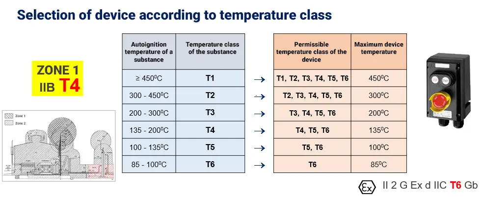
While in the case of most sources of ignition that can occur in the equipment the use of protection reduces the risk of its occurrence. However, temperature is different. The protection used does not eliminate it completely, but only limits it to a certain level. Which level?
The next position in the explosion-proof mark informs about this. For dust, the manufacturer gives a specific value for the maximum surface temperature, while for gases and vapors of flammable liquids the temperature class to which the surface temperature of the equipment is assigned.
Temperature class (gases and vapors)
The temperature class of the equipment is determined by its manufacturer. It is the maximum temperature that can occur on equipment surface under the most unfavorable operating conditions (e.g. highest ambient temperature, highest load on the equipment). If the device can reach different surface temperatures under different operating conditions, the manufacturer may specify different temperature classes in the rating plate, but this needs to be specified more precisely.
When selecting equipment for operation in a particular hazardous area, we must compare its temperature class with the temperature class of the gas and/or vapor that can create an explosive atmosphere in that area. The temperature class of the gas or vapor, in turn, depends on its self-ignition temperature. In other words, we must select the device so that the temperature on its surface expressed by its temperature class does not exceed the self-ignition temperature of the substance with which this device may come into contact.
Maximum surface temperature (dust)
The situation is slightly different for the maximum surface temperature of the equipment processing dust. In this case, the permissible temperature for equipment should be calculated according to the following table.
| T…oC | To verify whether a piece of equipment can safely operate in a hazardous area created by a particular combustible dust, it is necessary to make simple calculations of the acceptable temperature of its surface. This is to take into account the relevant safety margins. Dust cloud ignition temperature The temperature of vertical heated surfaces (inclined at an angle greater than 60°) must not exceed 2/3 of the value of the minimum ignition temperature of the dust cloud. Tcl safe = 2/3 • Tcl Dust layer ignition temperature The maximum permissible temperature of horizontal surfaces of equipment on which a layer of dust can form is determined taking into account the thickness of this layer. This temperature for equipment covered with a 5 mm or less dust layer should not exceed a value 75°C lower than the minimum ignition temperature of this dust layer. T5 mm safe = T5mm – 75°C For safety, it is most often assumed that the maximum surface temperature of the device must be lower than the lesser of the calculated values. Otherwise, the equipment in question does not meet your requirements. |
How do you determine the dust cloud temperature Tcl and the dust layer temperature T5mm?
Both values are determined in notified laboratories by testing a specific dust from the area of your facility. To do this, you need to take a sample from the area where the dust is expected to have the most demanding flammability and explosivity parameters (along with testing ignition temperatures, a number of other parameters are most often tested, e.g., lower explosion limit, minimum ignition energy, maximum explosion pressure or Kst).
If your plant has an Explosion Protection Document (EPD) drawn up based on an Hazard Identification and Risk Assessment (HIRA), then both temperatures should be found right there. You can also use literature data, nevertheless this solution will be subject to some inaccuracy (sometimes considerable).
In case you have trouble finding these values, please contact us. We have an extensive database with parameters of combustible dust, which we will make available to you for free. We can also perform commercial tests in the laboratory on your behalf. The latter is the best solution, because the mentioned parameters are not physical constants and their values, depend on several factors such as the fineness of the particles of the tested dust, its moisture content or admixture content.
Therefore, dust can have different combustible and explosive properties at different points in an installation. In extreme cases, the same dust from one point of the installation can be chemically safe (e.g., high moisture levels), while dust from another location can pose a high risk of explosion (e.g., dust from a dryer or mill). Below is an example of the parameters of wood dust in different parts of the installation:
| Dust sampling site | Lower Explosive Limit (LEL) [g/m3] | Minimum Ignition Energy (MIE) [mJ] | Ignition temperature of dust cloud Tcl [oC] | Ignition temperature of dust layer T5mm. [oC] | Maximum explosion pressure Pmax [bar] | Rate of pressure rise Kst [bar*m/s] |
| Przesiewacz | 30 | 173 | 430 | 330 | 8.5 | 57.2 |
| Szlifierki | 30 | 55 | 430 | 320 | 9.5 | 91.1 |
| Przesyp | 30 | 120 | 430 | 330 | 8.6 | 58.5 |
Because of the above, we should consider where these parameters will be highest, i.e. where in our installation the dust is finest and driest, and sample from there. Most often we recommend taking a sample from dust collectors. The amount of dust needed for full testing is approximately 3.5 kg (~7.7 lbs).
Practical exercises
Task 1
You are in search of a light fixture to be used in a chemical industrial plant. It will operate in explosion hazard zone 2 caused by hydrogen. You know that this gas belongs to explosion subgroup IIC and temperature class T1. Which device can work in these explosion hazard conditions?
Which light fixture(s) is/are appropriate?
| Light fixture 1 | Light fixture 2 | Light fixture 3 |
| II 2 D Ex tb IIIC T70°C Db II 3 G Ex ec IIC T4 Gc | II 3 D Ex tc IIIC T70°C Dc II 2 G Ex eb IIC T2 Gb | II 3 D Ex tc IIIC T170°C Dc II 3 G Ex ec IIA T1 Gc |
Answer:
Since we are dealing with gaseous explosive atmospheres, we focus only on the second line of the designation (one that refers to gases and liquid vapors). We know that the minimum requirements that the device must allow operation in the following conditions:
- gaseous explosive atmosphere,
- Zone 2
- explosion subgroup IIC
- temperature class T1
- ATEX type examination certificate is not required (Zone 2)
Light fixture 1
II 3 G Ex ec IIC T4 Gc
| II | the fixture can work in all industrial plants other than mining plants | ✔ |
| 3 G | the fixture can operate in explosion hazard Zone 2 caused by the presence of gases or liquid vapors | ✔ |
| IIC | the fixture can work with all explosion subgroups of gases and liquid vapors (IIA, IIB and IIC) | ✔ |
| T4 | the fixture can work with gases and liquid vapors with the following temperature classes: T1, T1, T2, T3 and T4 | ✔ |
| Conclusion: the fixture can operate under the set conditions. | ||
Fixture 2
II 2 G Ex eb IIC T2 Gb
| II | the fixture can work in all industrial plants other than mining plants | ✔ |
| 2 G | the fixture can operate in explosion hazard Zone 1 and Zone 2 caused by the presence of gases or liquid vapors | ✔ |
| IIC | the fixture can work with all explosion subgroups of gases and liquid vapors (IIA, IIB and IIC) | ✔ |
| T2 | the fixture can work with gases and liquid vapors with the following temperature classes: T1, and T2 | ✔ |
| Conclusion: the fixture can operate under the set conditions. | ||
Fixture 3
II 3 G Ex ec IIA T1 Gc
| II | the fixture can work in all industrial plants other than mining plants | ✔ |
| 3 G | the fixture can operate in explosion hazard Zone 2 caused by the presence of gases or liquid vapors | ✔ |
| IIA | the fixture can only work with substances from the IIA explosivity subgroup of gases and vapors | ⛌ |
| T1 | the fixture can work with gases and liquid vapors with T1 temperature class: | ✔ |
| Conclusion: the fixture cannot operate under the set conditions. | ||
Task 2
The situation as in task 1. except that, in addition to hydrogen, hydrogen sulfide may also appear in the working area of the fixture. You will find the parameters of both gases in the table below. For the record, we are dealing with explosion hazard Zone 2 and an industrial plant other than a mining plant.
| Explosivity subgroup | Temperature class | |
| Hydrogen | IIC | T1 |
| Hydrogen sulfide | IIB | T3 |
Which light fixture(s) is/are appropriate?
| Fixture 1 | Fixture 2 | Fixture 3 |
| II 2 D Ex tb IIIC T70°C Db II 3 G Ex ec IIC T4 Gc | II 3 D Ex tc IIIC T70°C Dc II 2 G Ex eb IIC T2 Gb | II 3 D Ex tc IIIC T70°C Dc II 3 G Ex ec IIA T1 Gc |
Answer:
Since we are dealing with a gaseous explosive atmosphere, we only focus on the second line of the marking, since it is the one that refers to gases and liquid vapors. This time we are dealing with two gases, and to select a device, we need to select the most demanding parameters. So, analyzing the situation described, we know that the minimum requirements that the device should meet must allow operation in the following conditions:
- gaseous explosive atmosphere,
- Zone 2
- explosion subgroup IIC (hydrogen)
- temperature class T3 (hydrogen sulfide)
- ATEX type examination certificate is not required (Zone 2)
Fixture 1
II 3 G Ex ec IIC T4 Gc
| II | the fixture can work in all industrial plants other than mining plants | ✔ |
| 3 G | the fixture can operate in explosion hazard Zone 2 caused by the presence of gases or liquid vapors | ✔ |
| IIC | the fixture can work with all explosion subgroups of gases and liquid vapors (IIA, IIB and IIC) | ✔ |
| T4 | the fixture can work with gases and liquid vapors with the following temperature classes: T1, T2, T3 and T4 | ✔ |
| Conclusion: the fixture can operate under the set conditions. | ||
Fixture 2
II 2 G Ex eb IIC T2 Gb
| II | the fixture can work in all industrial plants other than mining plants | ✔ |
| 2 G | the fixture can operate in explosion hazard Zone 1 and Zone 2 caused by the presence of gases or liquid vapors | ✔ |
| IIC | the fixture can work with all explosion subgroups of gases and liquid vapors (IIA, IIB and IIC) | ✔ |
| T2 | the fixture can work with gases and liquid vapors with the following temperature classes: T1, and T2, but it cannot be used for T3, T4, T5 and T6. | ⛌ |
| Conclusion: the fixture cannot operate under the set conditions. | ||
Fixture 3
II 3 G Ex ec IIA T1 Gc
| II | the fixture can work in all industrial plants other than mining plants | ✔ |
| 3 G | the fixture can operate in explosion hazard Zone 2 caused by the presence of gases or liquid vapors | ✔ |
| IIA | the fixture can only work with substances from the IIA explosivity subgroup of gases and vapors (it cannot operate with IIB and IIC) | ⛌ |
| T1 | the fixture can work with T1 gases and liquid vapors but it cannot be used for T2, T3, T4, T5 and T6. | ⛌ |
| Conclusion: the fixture cannot operate under the set conditions. | ||
Task 3
You want to select a lighting fixture for a facility in the food industry. The fixture will operate in a space where a 22 explosion hazard zone can occur due to flour and sugar dust. You have tested the explosivity of these dusts. Below you will find an excerpt from these tests:
| Ignition temperature of dust layer [5mm] | Ignition temperature of dust cloud | Explosivity subgroup | |
| Flour | 460°C | 390°C | IIIB |
| Sugar | 430°C | 310°C | IIIB |
Which light fixture(s) is/are appropriate?
| Fixture 1 | Fixture 2 | Fixture 3 |
| II 2 D Ex tb IIIC T70°C Db II 3 G Ex ec IIC T4 Gc | II 3 D Ex tc IIIA T70°C Dc II 2 G Ex eb IIC T2 Gb | II 3 D Ex tc IIIB T230°C Dc II 3 G Ex ec IIA T1 Gc |
Answer:
Since we are dealing with a dust explosive atmosphere, we focus only on the first line of the marking. By analyzing the situation, we know that the minimum requirements that the equipment should meet must allow operation in the following conditions:
- dust explosive atmosphere
- Zone 22
- explosion subgroup IIB
- maximum surface temperature of the device should be lower than 207°C
- ATEX type examination certificate is not required (Zone 22)
EXPLANATION: To calculate the maximum surface temperature of the device, we took the lower value of the ignition temperature of the dust layer (sugar – 430°C) and the ignition temperature of the dust cloud (sugar – 310°C). Then we substituted them into the formulas below and chose the lower of the results.
T5mm safe = T5mm – 75°C
Tcl safe = 2/3 • Tcl
Tcl = 310°C — 2/3 → 206 °C
T5mm = 430°C — 430 – 75 → 355 °C
CONCLUSION: maximum temperature of the external surface of the equipment must not exceed 206°C.
Fixture 1
II 2 D tb IIIC T70°C Db
| II | the fixture can work in all industrial plants other than mining plants | ✔ |
| 2 D | the fixture can operate in explosion hazard Zones 21 and 22 caused by the presence of combustible dusts | ✔ |
| IIIC | the fixture can work with all explosion subgroups of combustible dusts (IIIA, IIIB and IIIC) | ✔ |
| T70°C | maximum surface temperature of this equipment will not exceed 70°C, which is lower than 206°C | ✔ |
| Conclusion: the fixture can operate under the set conditions. | ||
Fixture 2
II 3 D Ex tc IIIA T70°C Dc
| II | the fixture can work in all industrial plants other than mining plants | ✔ |
| 3 D | the fixture can operate in explosion hazard Zone 22 caused by the presence of combustible dusts | ✔ |
| IIIA | the fixture can only work with substances from the IIIA explosivity subgroup of combustible dusts | ⛌ |
| T70°C | maximum surface temperature of this equipment will not exceed 70°C, which is lower than 206°C | ✔ |
| Conclusion: the fixture cannot operate under the set conditions. | ||
Fixture 3
II 3 D Ex tc IIIB T230°C Dc
| II | the fixture can work in all industrial plants other than mining plants | ✔ |
| 3 D | the fixture can operate in explosion hazard Zone 22 caused by the presence of combustible dusts | ✔ |
| IIIB | the fixture can work with substances from the IIIA or IIIB explosivity subgroup of combustible dusts | ✔ |
| T230°C | maximum surface temperature of this equipment will not exceed 230°C, which is lower than 206°C | ⛌ |
| Conclusion: the fixture cannot operate under the set conditions. | ||
A very important closing note:
Please note that when selecting equipment for operation in explosive atmospheres, we take into account their category, explosion sub-group and temperature class (equipment for gases and vapors of flammable liquids) or maximum surface temperature (equipment for dust). We are not at all interested in how the device is made (in a reinforced construction cover “e”, in a flameproof cover “d” or protected by a housing “t”). This information is important later, when operating, inspecting and maintaining the equipment.