

Can be used interchangeably with switches from leading manufacturers:

Suitable for Ex zones: 1, 2, 21, 22
Five safety features (overload, short-circuit, thermal, phase loss, undervoltage – optional)
The trip characteristics of the overload protection are similar to those of popular models from well-known manufacturers.
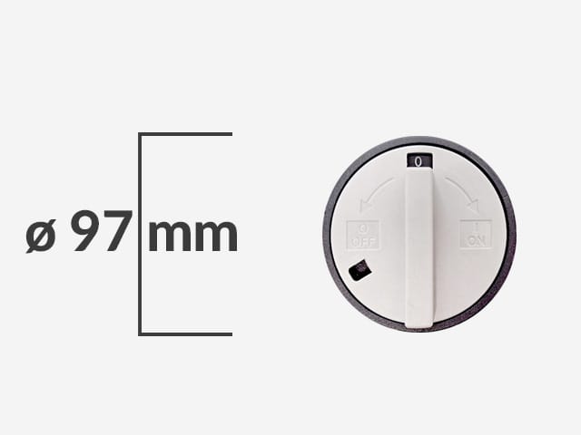
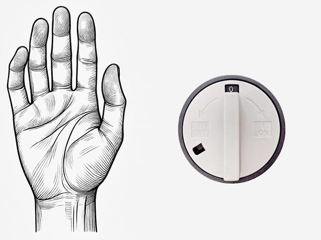
A large 97mm knob designed for use whilst wearing gloves
Can be locked in the OFF position (using a single padlock)


Downloads

Technical specifications:
Dimensions: see details below
Certifications:ATEX, IECEx
ATEX marking:
 II 2 G Ex db eb IIC T4/T5/T6 Gb
II 2 D Ex tb IIICT85°CDb
IECEx marking:
Housing material:GRP
Knob size: Ø97 mm
Permissible ambient temperature:-40°C to +55°C
Protection rating:IP66
Rated voltage:440V
Protection features: overload; phase loss; short-circuit; thermal; undervoltage (optional);
Overload trip setting range: 0.1 to 25 A
Motor starting capacity in category AC3: up to440 V / 25 A
Main contacts: 1to10 mm²
(from 6 to 10 mm² when using crimp sleeves)
Auxiliary contacts:1 to2.5 mm²
Rated capacity of auxiliary contacts: AC151A / 230V
Rated breaking capacity: high– up to 65 kA
Price:


5 types of security measures – exactly the same as those offered by the market leaders
01/ OVERLOAD
02/ SHORT CIRCUITS
03/ THERMAL
04/ PHASE DROPOFF
05/ SUB-VOLTAGE (optional)
Overload protection
Motor circuit breakers for potentially explosive atmospheres are fitted with built-inoverload protection. This protects the motor not only againstprolonged overloads, but also againsttoo frequent startsorshort-term overloads, which can lead to the windings overheating. The device’s rated operating voltage is 440 V.
The practical aspect
It protects the motor from prolonged operation at loads exceeding its rated power, which could cause the windings to overheat, damage the insulation and shorten the motor’s service life.
Technical principle of operation:
These are most commonly implemented using a bimetallic strip or thermal sensors embedded in the windings. An increase in current causes the sensing element to heat up, and once a set temperature is reached, the circuit is mechanically opened.
A practical example:
In a belt conveyor, the overload protection will shut down the motor if the belt becomes jammed by an obstruction, before the windings burn out.
Setting ranges: 0.1–25 A
The appropriate trip current is preset during manufacture – always in accordance with the customer’s requirements and the application of the circuit breaker in question. It is also possible to adjust the range on site.
The overload range values are shown in the configuration table.
Phase loss protection
The practical aspect
It prevents a three-phase motor from operating when one of the phases is missing, as this would result in an uneven load on the windings, increased current draw in the remaining phases, and a risk of damage.
Technical principle of operation:
The control system monitors the presence of all three phases. If a signal is missing from any one of them, the motor is switched off immediately.
A practical example:
In an industrial pumping station, phase failure protection will shut down the pump should one of the phases fail, thereby preventing it from overheating and breaking down.
Short-circuit protection
The practical aspect
It protects the motor, cables and control equipment from the effects of short circuits, which can lead to damage to the system or a fire.
Technical principle of operation:
An electromagnetic trip device is used, which responds to a sudden, very large surge in current. A strong magnetic field attracts the mechanism’s core, causing the contacts to open immediately.
A practical example:
In a compressor motor, if the winding insulation breaks down, the short-circuit protection will cut off the power supply in a fraction of a second, protecting the system from the effects of an electric arc.
Thermal protection
The practical aspect
It protects the engine from overheating, whatever the cause — whether it be overload, poor ventilation, high ambient temperatures or mechanical problems.
Technical principle of operation:
Temperature sensors (e.g. PTC thermistors or thermal cut-outs) are built into the motor windings. Once the limit temperature is reached, the signal from the sensor causes the motor to shut down or the motor cut-out to trip.
A practical example:
In a fan operating in a high-temperature zone, a thermal sensor will shut down the motor if the temperature of the windings exceeds a safe level.
Overvoltage release (U)
Motor circuit breakers designed for use in potentially explosive atmospheres can be optionally fitted withan undervoltage release. Its function is to automatically switch off the device should the supply voltage drop below a safe level. This protects both the motor itself and other components of the installation from the effects of unstable power supply conditions. The circuit breaker prevents the motor from restarting automatically once the voltage returns, which is essential for safety in Ex zones.
The practical aspect
It prevents the motor from operating at a voltage lower than the permissible level, which could lead to an increase in current, a drop in torque and overheating of the windings.
Technical principle of operation:
The monitoring system constantly checks the voltage level. If it falls below the set threshold, the mechanism disconnects the circuit and prevents it from being reconnected until the correct voltage is restored.
A practical example:
In the packaging line, the undervoltage protection will shut down the feeder motor if the voltage drops to such an extent that it could stop mid-cycle and be damaged.
Overload trip characteristics
The graph shows the relationship between the tripping time and the current value (expressed as a multiple of the rated current (In) at an ambient temperature of 30°C). This characteristic ensures an effective response to both light and heavy overloads:
for high overloads (e.g. 8–10 ×In) – in a matter of milliseconds,
For low overloads (1.2–2 ×In), the response occurs after a few to several minutes.

Motor circuit breakers for potentially explosive atmospheres
HARDO HCS1P series motor circuit breakers are designed for use in potentially explosive atmospheres, in zones 1, 2, 21 and 22. Their primary type of protection in terms of explosion safety is Ex e (reinforced construction). In addition, HARDO Ex motor circuit breakers feature overload protection and can also be equipped with undercurrent protection and auxiliary contacts (1NO + 1NC).
Ex HCS1P motor circuit breakers are characterised bya highrated switching capacity – up to 65 kA – ensuring effective operation even in installations with high short-circuit energy. When controlling motors in category AC3,the device can handle loads up to 440V / 25A.
Principle of operation based on the circuit diagram
The diagram shows the basic connections for the main circuits (L1, L2, L3 – T1, T2, T3), the overvoltage trip control circuit, and the auxiliary contacts (13–14 and 21–22). Once power is applied and the circuit is activated, the motor is switched on. In the event of an overload or a voltage drop, the trip units cut off the power supply. The operating contact category is AC-3
The main terminals are designed for cables with a cross-section of 1 to 10 mm² (or 6–10 mm² when using crimp sleeves), allowing for flexible adaptation to a variety of installations.

Auxiliary contacts: 1 NO + 1 NC
Ex-rated motor circuit breakers may be fitted withauxiliary contacts(one normally open and one normally closed), which are independent of the main contacts and can be used for:
transmitting the circuit breaker’s operating status signal to the master system (e.g. a PLC),
triggering a visual or audible signal,
preventing other devices in the system from starting up.
The auxiliary contacts are rated AC15 (1A/230V). The terminals for the auxiliary contacts are designed to accommodate wires with a cross-sectional area of 1 to 2.5 mm².
Circuit breaker enclosure: durability and safety
The housing of the motor circuit breaker for potentially explosive atmospheres is made of unsaturated polyester resin. The product is reinforced with glass fibre and contains mineral fillers. In the event of a fire, the product does not melt, drip or emit excessive smoke. The product contains no halogens, heavy metals or any substances listed on the REACH SVHC list.
The housing offers high mechanical and chemical resistance.
The material used for the outer casing contains additives that reduce static build-up, thereby eliminating the risk of an explosive atmosphere being ignited as a result of an electrostatic discharge.
Configurations
|
DŁAWNICE
|
ZABEZPIECZENIA PRZECIĄŻENIOWE
|
ZABEZPIECZENIA ZANIKU FAZY
|
ZABEZPIECZENIA ZWARCIOWE
|
THERMAL PROTECTION |
UNDERVOLTAGE PROTECTION |
AUXILIARY CONTACTS NO + NC |
ORDER NUMBER |
|---|---|---|---|---|---|---|---|
|
2 x M25 |
YES (0.1–0.16 A) |
YES |
YES |
YES |
NO |
NO |
HCS1P 252616 S01211 |
|
2 x M25 |
YES (0.16–0.25 A) |
YES |
YES |
YES |
NO |
NO |
HCS1P 252616 S01221 |
|
2 x M25 |
YES (0.25–0.4 A) |
YES |
YES |
YES |
NO |
NO |
HCS1P 252616 S01231 |
|
2 x M25 |
YES (0.4–0.63 A) |
YES |
YES |
YES |
NO |
NO |
HCS1P 252616 S01241 |
|
2 x M25 |
YES (0.63–1.0 A) |
YES |
YES |
YES |
NO |
NO |
HCS1P 252616 S01251 |
|
2 x M25 |
YES (1.0–1.6 A) |
YES |
YES |
YES |
NO |
NO |
HCS1P 252616 S01261 |
|
2 x M25 |
YES (1.6–2.5 A) |
YES |
YES |
YES |
NO |
NO |
HCS1P 252616 S01271 |
|
2 x M25 |
YES (2.5–4.0 A) |
YES |
YES |
YES |
NO |
NO |
HCS1P 252616 S01281 |
|
2 x M25 |
YES (4.0–6.3 A) |
YES |
YES |
YES |
NO |
NO |
HCS1P 252616 S01291 |
|
2 x M25 |
YES (6.3–10.0 A) |
YES |
YES |
YES |
NO |
NO |
HCS1P 252616 S01301 |
|
2 x M25 |
YES (10.0–16.0 A) |
YES |
YES |
YES |
NO |
NO |
HCS1P 252616 S01311 |
|
2 x M32 |
YES (16.0–20.0 A) |
YES |
YES |
YES |
NO |
NO |
HCS1P 252616 S01321 |
|
2 x M32 |
YES (20.0–25.0 A) |
YES |
YES |
YES |
NO |
NO |
HCS1P 252616 S01331 |
|
DŁAWNICE
|
ZABEZPIECZENIA PRZECIĄŻENIOWE
|
ZABEZPIECZENIA ZANIKU FAZY
|
ZABEZPIECZENIA ZWARCIOWE
|
THERMAL PROTECTION |
UNDERVOLTAGE PROTECTION |
AUXILIARY CONTACTS NO + NC |
ORDER NUMBER |
|---|---|---|---|---|---|---|---|
|
3 x M25 |
YES (0.1–0.16 A) |
YES |
YES |
YES |
YES |
NO |
HCS1P 252616 S01212 |
|
3 x M25 |
YES (0.16–0.25 A) |
YES |
YES |
YES |
YES |
NO |
HCS1P 252616 S01222 |
|
3 x M25 |
YES (0.25–0.4 A) |
YES |
YES |
YES |
YES |
NO |
HCS1P 252616 S01232 |
|
3 x M25 |
YES (0.4–0.63 A) |
YES |
YES |
YES |
YES |
NO |
HCS1P 252616 S01242 |
|
3 x M25 |
YES (0.63–1.0 A) |
YES |
YES |
YES |
YES |
NO |
HCS1P 252616 S01252 |
|
3 x M25 |
YES (1.0–1.6 A) |
YES |
YES |
YES |
YES |
NO |
HCS1P 252616 S01262 |
|
3 x M25 |
YES (1.6–2.5 A) |
YES |
YES |
YES |
YES |
NO |
HCS1P 252616 S01272 |
|
3 x M25 |
YES (2.5–4.0 A) |
YES |
YES |
YES |
YES |
NO |
HCS1P 252616 S01282 |
|
3 x M25 |
YES (4.0–6.3 A) |
YES |
YES |
YES |
YES |
NO |
HCS1P 252616 S01292 |
|
3 x M25 |
YES (6.3–10.0 A) |
YES |
YES |
YES |
YES |
NO |
HCS1P 252616 S01302 |
|
3 x M25 |
YES (10.0–16.0 A) |
YES |
YES |
YES |
YES |
NO |
HCS1P 252616 S01312 |
|
2 x M32 + 1 x M25 |
YES (16.0–20.0 A) |
YES |
YES |
YES |
YES |
NO |
HCS1P 252616 S01322 |
|
2 x M32 + 1 x M25 |
YES (20.0–25.0 A) |
YES |
YES |
YES |
YES |
NO |
HCS1P 252616 S01332 |
|
DŁAWNICE
|
ZABEZPIECZENIA PRZECIĄŻENIOWE
|
ZABEZPIECZENIA ZANIKU FAZY
|
ZABEZPIECZENIA ZWARCIOWE
|
THERMAL PROTECTION |
UNDERVOLTAGE PROTECTION |
AUXILIARY CONTACTS NO + NC |
ORDER NUMBER |
|---|---|---|---|---|---|---|---|
|
3 x M25 |
YES (0.1–0.16 A) |
YES |
YES |
YES |
NO |
YES |
HCS1P 252616 S01213 |
|
3 x M25 |
YES (0.16–0.25 A) |
YES |
YES |
YES |
NO |
YES |
HCS1P 252616 S01223 |
|
3 x M25 |
YES (0.25–0.4 A) |
YES |
YES |
YES |
NO |
YES |
HCS1P 252616 S01233 |
|
3 x M25 |
YES (0.4–0.63 A) |
YES |
YES |
YES |
NO |
YES |
HCS1P 252616 S01243 |
|
3 x M25 |
YES (0.63–1.0 A) |
YES |
YES |
YES |
NO |
YES |
HCS1P 252616 S01253 |
|
3 x M25 |
YES (1.0–1.6 A) |
YES |
YES |
YES |
NO |
YES |
HCS1P 252616 S01263 |
|
3 x M25 |
YES (1.6–2.5 A) |
YES |
YES |
YES |
NO |
YES |
HCS1P 252616 S01272 |
|
3 x M25 |
YES (2.5–4.0 A) |
YES |
YES |
YES |
NO |
YES |
HCS1P 252616 S01283 |
|
3x M25 |
YES (4.0–6.3 A) |
YES |
YES |
YES |
NO |
YES |
HCS1P 252616 S01293 |
|
3x M25 |
YES (6.3–10.0 A) |
YES |
YES |
YES |
NO |
YES |
HCS1P 252616 S01303 |
|
3x M25 |
YES (10.0–16.0 A) |
YES |
YES |
YES |
NO |
YES |
HCS1P 252616 S01313 |
|
2 x M32 + 1 x M25 |
YES (16.0–20.0 A) |
YES |
YES |
YES |
NO |
YES |
HCS1P 252616 S01323 |
|
2 x M32 + 1 x M25 |
YES (20.0–25.0 A) |
YES |
YES |
YES |
NO |
YES |
HCS1P 252616 S01333 |
|
DŁAWNICE
|
ZABEZPIECZENIA PRZECIĄŻENIOWE
|
ZABEZPIECZENIA ZANIKU FAZY
|
ZABEZPIECZENIA ZWARCIOWE
|
THERMAL PROTECTION |
UNDERVOLTAGE PROTECTION |
AUXILIARY CONTACTS NO + NC |
ORDER NUMBER |
|---|---|---|---|---|---|---|---|
|
4 x M25 |
YES (0.1–0.16 A) |
YES |
YES |
YES |
YES |
YES |
HCS1P 252616 S01214 |
|
4 x M25 |
YES (0.16–0.25 A) |
YES |
YES |
YES |
YES |
YES |
HCS1P 252616 S01224 |
|
4 x M25 |
YES (0.25–0.4 A) |
YES |
YES |
YES |
YES |
YES |
HCS1P 252616 S01232 |
|
4 x M25 |
YES (0.4–0.63 A) |
YES |
YES |
YES |
YES |
YES |
HCS1P 252616 S01234 |
|
4 x M25 |
YES (0.63–1.0 A) |
YES |
YES |
YES |
YES |
YES |
HCS1P 252616 S01244 |
|
4 x M25 |
YES (1.0–1.6 A) |
YES |
YES |
YES |
YES |
YES |
HCS1P 252616 S01254 |
|
4 x M25 |
YES (1.6–2.5 A) |
YES |
YES |
YES |
YES |
YES |
HCS1P 252616 S01264 |
|
4 x M25 |
YES (2.5–4.0 A) |
YES |
YES |
YES |
YES |
YES |
HCS1P 252616 S01274 |
|
4 x M25 |
YES (4.0–6.3 A) |
YES |
YES |
YES |
YES |
YES |
HCS1P 252616 S01284 |
|
4 x M25 |
YES (6.3–10.0 A) |
YES |
YES |
YES |
YES |
YES |
HCS1P 252616 S01304 |
|
4 x M25 |
YES (10.0–16.0 A) |
YES |
YES |
YES |
YES |
YES |
HCS1P 252616 S01314 |
|
2 x M32 + 2 x M25 |
YES (16.0–20.0 A) |
YES |
YES |
YES |
YES |
YES |
HCS1P 252616 S01324 |
|
2 x M32 + 2 x M25 |
YES (20.0–25.0 A) |
YES |
YES |
YES |
YES |
YES |
HCS1P 252616 S01334 |
- Last digit of the order number:
- 1 – basic version without overvoltage release and auxiliary contacts
- 2 – overvoltage release
- 3 – auxiliary contacts: 1 NO + 1 NC
- 4 – overvoltage release and auxiliary contacts: 1 NO + 1 NC

ATEX Directive requirements for motor connectors
Electric motors used in potentially explosive atmospheres require special protection against overloads and short circuits, in accordance with the requirements of the ATEX Directive (2014/34/EU) and standards IEC 60079-14 and PN-EN 60079-0.
What are the risks for engines?
Phenomena such as overloads and short circuits can lead to excessive heating of the motor windings, damage to the insulation, and the formation of electric arcs and sparks. In the presence of explosive mixtures (gases, vapours of flammable liquids or dust), this may lead to the ignition of an explosive atmosphere.
How to choose the right equipment
Any electrical equipment operating in a potentially explosive atmosphere must be designed, selected and installed in accordance with the specific requirements arising from the Ex zone classification and the equipment category.
The motor coupler as the final component in the process
The entire drive system must comply with the temperature class requirements (e.g. T3, T4) and be appropriately selected for the zone type (0, 1, 2 for gases or 20, 21, 22 for dusts) and explosion group.
Reducing the risk of ignition
The implementation of the protective measures described reduces the risk of ignition to an acceptable level and ensures the safe, reliable and compliant operation of electric drives in potentially explosive atmospheres.